Valves
SAFETY FIRST: Protective gloves and eyewear are recommended at this point.
Removal
Record the position of all parts so they can be returned to their proper place during reassembly.
On the 1992 the shims must be removed be removed before the valves can be removed.
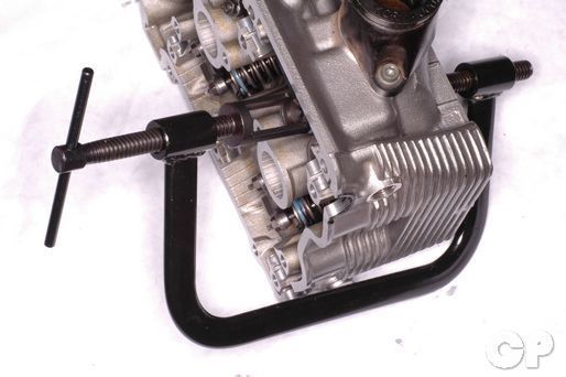


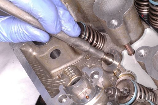
Push down the valve springs with a valve spring compressor.
Special Tools-
Valve Lifter: 09916-14510
Valve Lifter Attachment: 09916-14910
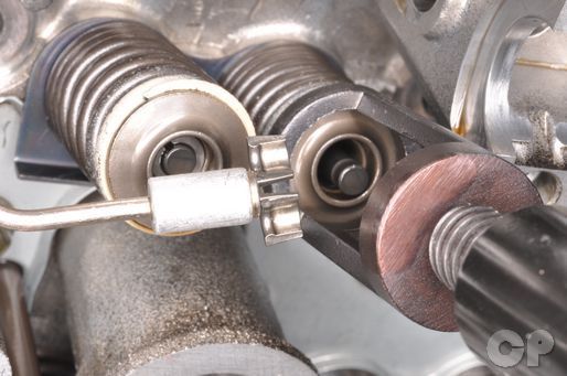
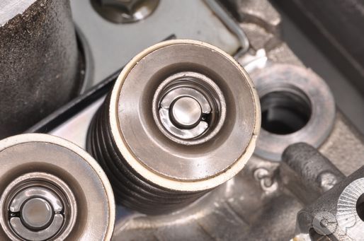
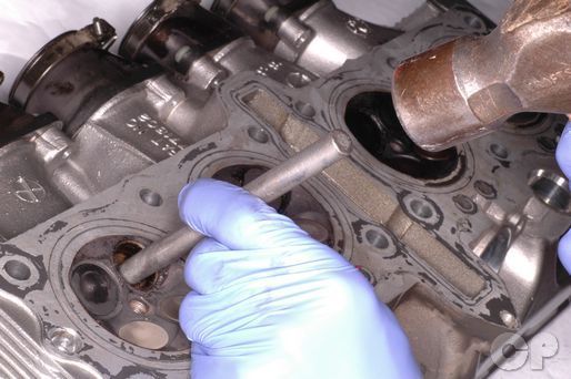
Remove the split keepers with tweezers or a magnet. There are two per valve.
Remove the spring retainer.


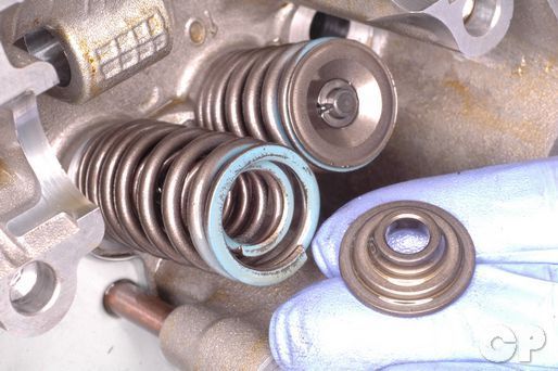
Remove the inner and the outer valve springs.


Push the valve out from the combustion chamber.


Remove the spring seat. mark the


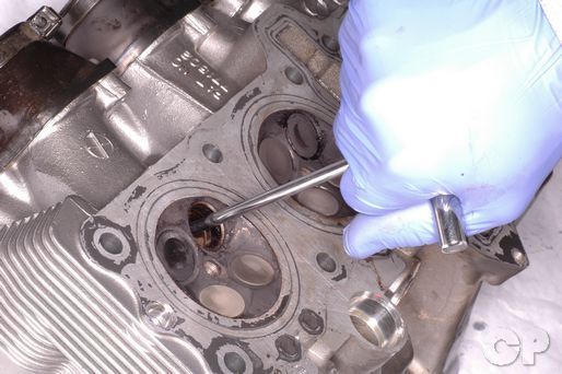
Remove the valve seal from the valve guide. Pry the seal off gently with a small screwdriver or pick.
Inspection


Measure the free length the valve springs with vernier calipers. Replace the springs if they are below the service limit.
| Model (Item) | Spring | Limit mm (in) |
| 600 (IN. and EX.)
1988 - 1991 |
INNER | 35.0 (1.38) |
| OUTER | 38.4 (1.51) | |
| 600 (IN. and EX.)
1992 - 1997 |
INNER | 39.1 (1.38) |
| OUTER | 41.6 (1.64) | |
| 750 (IN. and EX.) | INNER | 33.9 (1.33) |
| OUTER | 37.3 (1.47) |


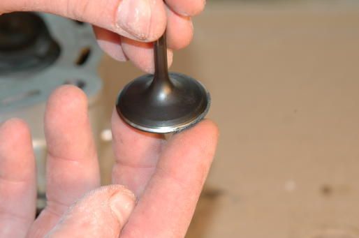
Inspect the valves for damage and burning. Measure the valve stem diameter where the valve makes contact with the guide. If the measurement is below specification replace the valve.
| Item | Standard mm (in) |
| IN. | 4.965-4.980 (0.1955-0.1961) |
| EX.
|
4.945-4.960 (0.1947-0.1953) |
| EX. 600 92-97 | 4.955-4.970 (0.1950-0.1957) |
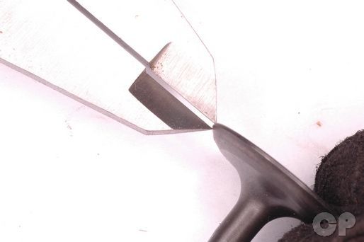
Inspect the valve face for wear and damage. Measure the valve face margin with vernier calipers.
(Valve Face Thickness Service Limit: 0.5 mm or 0.02 in)
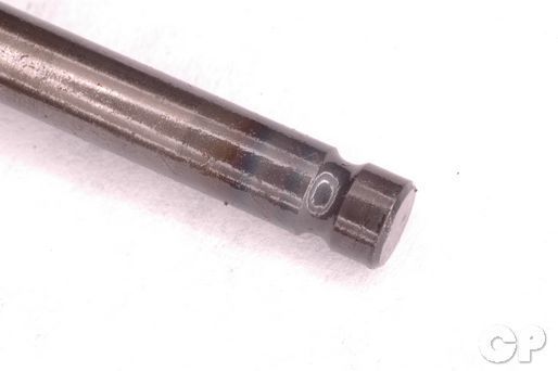
Inspect the end of the valve stem for damage and wear. Measure the length of the valve stem end. Replace the valve if the end doesn't meet the service limit.
| ITEM | LIMIT mm (in) | |
| 600 | IN. and EX. | 2.5 (0.10) |
| 750 | IN. and EX. | 2.3 (0.09) |
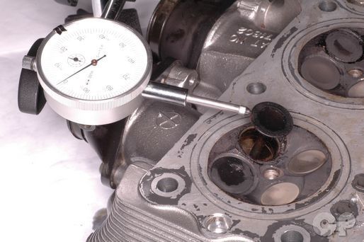 Lift the valve around 10 mm (0.39 in) from the cylinder head and check for valve stem deflection with a dial gauge and magnetic stand. If the deflection is out of specification inspect the valve and valve guide and replace the components as needed.
Special Tools-
Dial Gauge (1/100 mm): 09900-20606
Magnetic Stand: 09900-20701
| Item | Standard mm (in) | Limit |
| IN. | 0.020-0.047 (0.0008-0.0019) | 0.35 (0.014) |
| EX. | 0.040-0.067 (0.0016-0.0026) | 0.35 (0.014) |
| EX. 600 92-97 | 0.030-0.057 (0.0012-0.0022) | 0.35 (0.014) |
Ream the valve guides before measuring them to remove any carbon build up. Insert the reamer through the valve opening in the combustion chamber. Only turn the reamer clockwise.
(Valve Stem Deflection Service Limit: 0.35 mm or 0.014 in)
Special Tools-
Valve Guide Reamer: 09916-34580
Valve Guide Reamer Handle: 09916-34541
Measure the inside diameter of the valve guides. Subtract the diameter of the valve stem from the valve guide to calculate the stem-to-guide clearance. If the stem-to-guide clearance exceeds the service limit replace both the valve and the valve guide.
| ITEM | STANDARD mm (in) |
| IN. | 0.020-0.047 (0.0008-0.0019) |
| EX. 600 | 0.030-0.057 (0.0012-0.0022) |
| EX. 750 | 0.020-0.047 (0.0008-0.0019) |
Valve Guides
If you need to replace your valve guides we recommend taking your cylinder head to a machine shop. Even professional mechanics usually will take this type of work to a machine shop. You will need to resurface the valve seats when you replace the guides. Also, the valve guides must be replaced with oversized components.
To remove the valve guides you must evenly heat the head. Do not use a torch because of the possibility of warping the head.
Gently hammer out the valve guide using a valve guide driver. Insert the driver through the valve opening in the combustion chamber and drive out the guide towards the top of the cylinder head.
Special Tool-
Valve Guide Remover /Installer: 09916-44310
If you removed the valve guides install the new guides with new O-rings. Oil the valve guide hole before installation. Use the same driver you used to remove the guides to drive in the new ones. Drive in the guides from the top of the cylinder head, and take care to keep from damaging them.
When the valve guides have been installed you must ream them to be ready to accept the valves. Use a valve guide reamer with cutting oil. Insert the reamer through the valve opening in the combustion chamber. Only turn the reamer clockwise.
Valve Seat
Coat the valve face with a thin layer of Prussian blue and install the valve into the guide.
Using a valve lapping tool, spin the valve in a back and forth circular motion while applying downward pressure onto the valve.
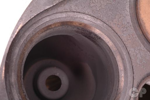
Pull the valve up and look for a complete impression of the Prussian blue all the way around valve seat. Measure the width of the valve seat and compare it to the specification. If there is a break in the compound on the seat or the width doesn't meet the service limit, you will need to re-cut the valve seat.
(Valve Seat Width: 0.9 - 1.1 mm or 0.035 - 0.043 in)
Valve Seat Cutting
If you need to replace or resurface your valve seats we recommend taking your cylinder head to a machine shop. Even professional mechanics usually will take this type of work to a machine shop.
| Model | Intake | Exhaust | Angle |
| 600 and 750 | N-122 | N-122 | 45° |
| 600 and 750 | N-212 | N-125 | 75° |
| 750 | N-126 | ------ | 30° |
| 600 and 750 | N-121 | N-121 | 15° |
Solid Pilots-
N-100-5.0 (N-121, 122, and 125)
N-140-5.0 (N-212)
Measure and inspect the valve seat after each cut.
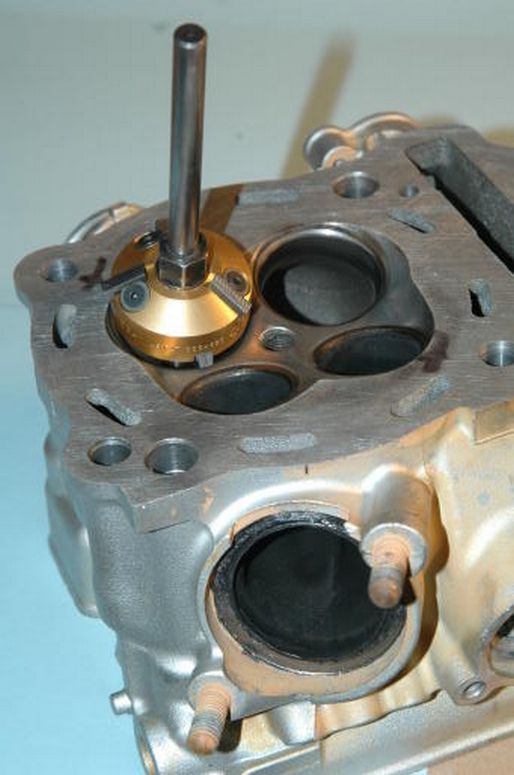
Install the pilot guide into the valve guide and rotate it 1/2 a turn while pushing it in.
Install the 45 degree cutter onto the pilot making sure it fits snug.
Rotate the cutter one to two times in a clockwise direction to clean up the seat.
Note: Never turn a valve seat cutter counterclockwise as this will dull the blades.
If pitting is still evident repeat the process.
NOTE: Cut only the minimum that you need.
If the contact area on the exhaust is too wide or high you will need to use the 15° and 75° cutters (30° and 75° for 750 intake). This will help narrow and lower the fit of the valve to the seat.
If the contact area is too low or narrow you will need to use the 45° cutter.
After making the other cuts, use the 45° degree cutter to clean up any imperfections or burrs that remain on the valve seat.
Assembly
Lubricate the new oil seals with fresh engine oil and press them straight onto the valve guides.
Install the spring seats.
Lubricate the valve guide and valve stem with moly paste and insert the valve into the cylinder head. Turn the valve slowly as it is inserted.
Suzuki Moly Paste: 99000-25140
If you are installing a new valve you must ream the valve guide. Make sure the valve will move smoothly in the valve guide without wobble.
Install the valve springs with the tightly coiled side facing down.
Place the spring retainer on the spring and push down the valve springs with a valve spring compressor.


Apply grease to the inside of the split keepers. Apply a dab of grease to the end of a flat blade screwdriver. Set the keeper in the grease on the screwdriver and insert it onto the valve stem. Repeat this with the other keeper.
Give the valve a tap with a rubber mallet. If the keepers give way put them back in and make sure they are fully seated. Test them one more time to make sure they are properly installed.
To install the cylinder head see the Cylinder Head Installation topic.
Copyright 2025 - Cyclepedia Press LLC

Note: If you are viewing this document offline be sure to visit the latest version online at http://www.cyclepedia.com before attempting any repairs. Updates are made without notice.