Transmission Removal
SAFETY FIRST: Protective gloves and eyewear are recommended at this point.
Removal
Split the crankcases. See the Crankcase Splitting topic for more information.
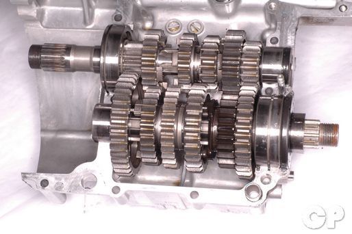


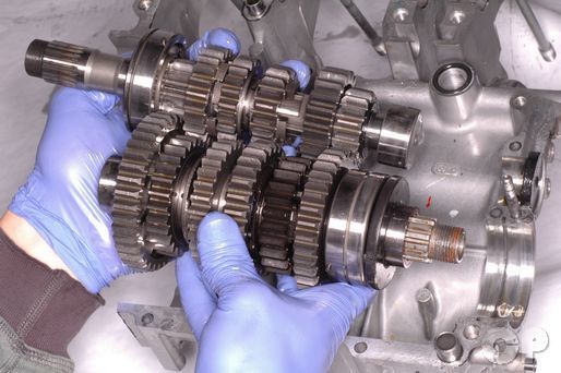
Lift the mainshaft and countershaft out of the lower crankcase. If necessary tap on the end of the countershaft with a rubber mallet to free the shafts from the case half.
To disassemble the transmission shafts see the Transmission Shafts topic.


Remove the mainshaft clutch push rod seal from the crankcase.


Remove the C-rings from the cases.


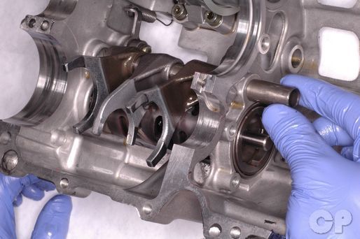
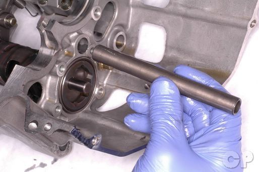
Remove the bearing pins.
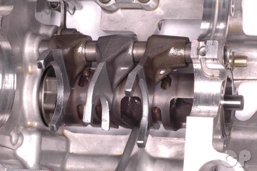
The shift drum, shift forks, and shift fork shaft are located in the upper crankcase half.


Slide the shift fork shaft out and remove the shift forks.
Remove the shift fork shaft. Inspect the shift fork shaft for wear and damage.
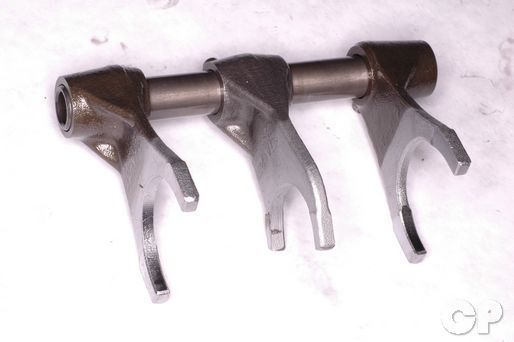
The three shift forks are responsible for sliding the gears on the transmission shafts to select the proper gear ratio. If the forks are damaged the motorcycles ability to shift gears will suffer. The two outside shift forks fit in the grooves on the C5 and C6 countershaft gears. The middle shift fork fits in the groove on the M3/4 combo gear on the mainshaft.
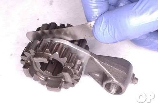
Measure the clearance between the shift forks and their respected gear grooves with a feeler gauge. If the service limit is exceeded inspect the gears and shift forks and replace them as needed.
| STANDARD mm (in) | LIMIT |
| 0.1-0.3 (0.004-0.012) | 0.50 (0.020) |
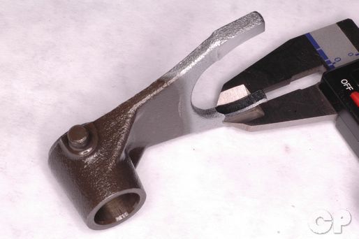
Inspect the shift forks for wear and damage. Measure the ears of the shift fork with a micrometer or vernier calipers.
| SHIFT FORK | STANDARD mm (in) |
| Countershaft (outside) | 4.6-4.7 (0.181-0.185) |
| Mainshaft (middle) | 4.8-4.9 (0.189-0.193) |
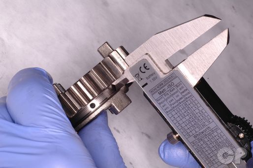
Measure the width of the shift fork grooves in their respected gears.
| GEAR | STANDARD mm (in) |
| C5 and C6 | 4.8-4.9 (0.189-0.193) |
| M3/4 | 5.0-5.1 (0.197-0.201) |


Unhook the gearshift cam stopper spring from its notch on the lower crankcase half.


Remove the snap ring from the end of the shift drum with snap ring pliers.


Remove the shift drum from the lower crankcase half. Inspect the shift drum for wear and damage.
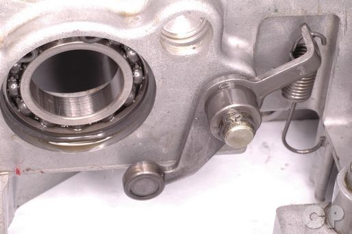


Remove the snap ring from the stopper arm post bolt with snap ring pliers.
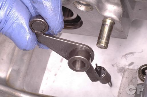
Remove the stopper arm and spring from the post bolt.


Remove the Stopper arm post bolt with a 12 mm socket.
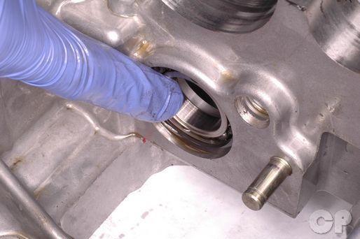
Turn the shift drum bearing with a finger. The bearing should turn smoothly without noise or roughness. Replace the bearing as needed.
Installation
Apply a small amount of blue Loctite to the stopper arm post bolt threads. Insert the stopper arm bolt and tighten it securely with a 12 mm socket.


Install the stopper arm and spring onto the stopper arm post bolt. Install a new snap ring into the groove on the end of the stopper arm post bolt.
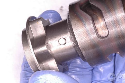


Line up the pin on the shift drum with the slot in the stopper plate.
Lubricate the shift drum bearings with fresh engine oil. Apply moly paste to the shift drum cam grooves. Install the shift drum into the upper crankcase half.
Suzuki Moly Paste: 99000-25140
Install a new snap ring onto the end of the shift drum with snap ring pliers.
Use a spring puller to hook the stopper arm spring around its notch on the lower crankcase half.
Lubricate the shift fork shaft with a light coat of moly paste.
Suzuki Moly Paste: 99000-25140
Insert the shift fork shaft through the shift forks as shown. Fit the shift fork guide pins into the cam grooves on the shift drum.


Make sure the shift forks are installed in the correct position.
Install the bearing pins into the upper crankcase half.
Install the C-rings into the upper case half.
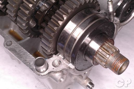
Place the transmission shafts into the upper crankcase. Fit the bearings onto the bearing pins and C-rings. Coat the lips of the new mainshaft oil seal in Suzuki "A" grease. Install the new oil seal onto the end of the mainshaft.
Suzuki Super Grease "A": 99000-25030
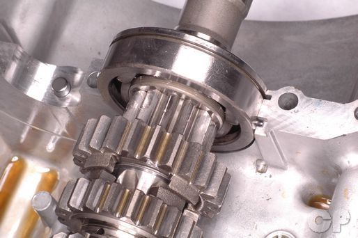


Fit the mainshaft bearing dowel pin into its recess as shown.


Fit the countershaft bearing dowel pin into its recess as shown.
Lubricate the transmission bearings with fresh engine oil. Turn the transmission shafts and make sure they function correctly. With the shift drum in neutral you should be able to hold the counter shaft still and turn the mainshaft freely.
Assemble the crankcases. See the Crankcase Assembly topic for more information.
Copyright 2025 - Cyclepedia Press LLC

Note: If you are viewing this document offline be sure to visit the latest version online at http://www.cyclepedia.com before attempting any repairs. Updates are made without notice.