Cylinder and Piston
SAFETY FIRST: Protective gloves and eyewear are recommended at this point.
Disassembly
Remove the cylinder head. See the Cylinder Head topic for more information.


Remove the oil pipes from the crankcase.
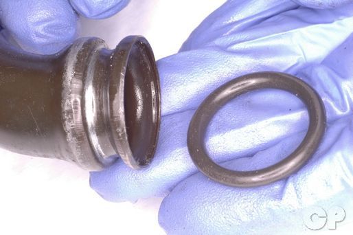
Remove the O-rings from the oil pipes.
Remove the air injection system hoses from the cylinders if your model is equipped with this system. See the Emissions topic for more information.


Remove the cylinder base nut with a 10 mm wrench.


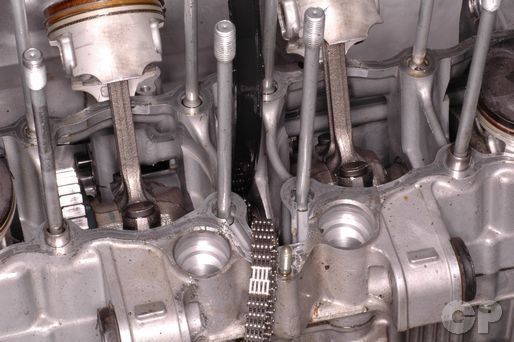
Grip the cylinder block on each side and lift it off of the crankcase. If needed, you can gently tap on the areas without cooling fins with a plastic mallet to free the dowel pins. Guide the cam chain through its opening in the cylinder. Make sure the cam chain doesn't fall into the crankcase.


Remove the base gasket


Remove the dowel pins.
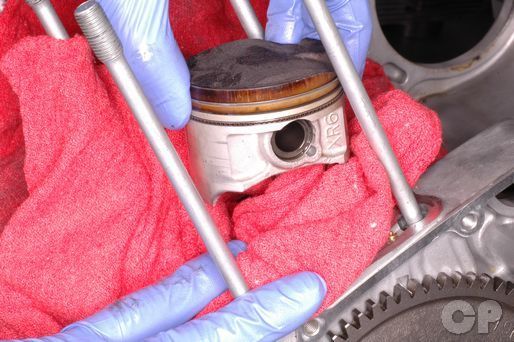
Place a clean shop towel under and around the base of the piston to prevent any parts or debris from falling into the crankcase.
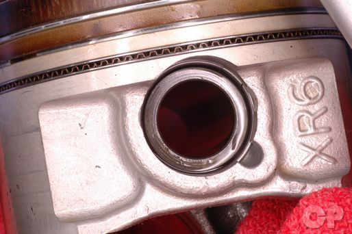


Remove the piston pin clips with a pick or needle nose pliers. Discard the piston pin clips.
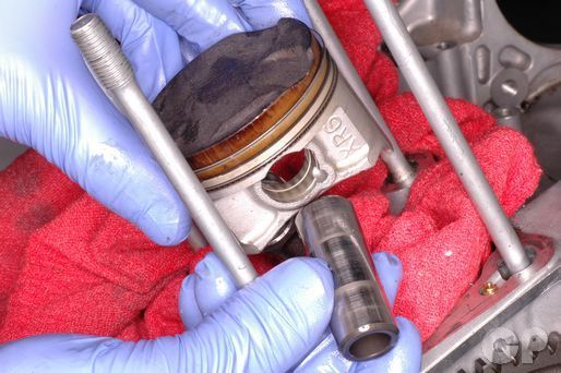
Remove the piston pins and the pistons. Take note of the location of the components so they can be returned to the proper place if reused.
Clean off the cylinder mating surface, but take care to keep debris from falling into the crankcase.


Spread the piston rings and lift them off opposite the gap. Spread the rings the minimum amount during removal. The rings can be easily damaged.
Clean the carbon build up off of the piston with a stiff bristled plastic brush. Never use a wire brush to clean a piston. Also clean out the ring grooves. You can use an old ring to scrape out any carbon build up in the grooves.
Inspection
Oversized rings and pistons are available in 0.5 and 1.0 mm over.
Measure the diameter of the cylinders front to back and side to side at three different height levels. Inspect the cylinders for wear and damage. If a cylinder is out of specification the cylinder block must be replaced or all of the cylinders must be overhauled. There are two sizes of oversized pistons available. All of the Pistons and rings must be changed to oversized parts.
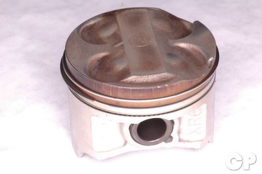
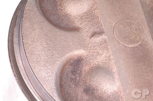
Inspect the piston for damage, wear, and discoloration.


Measure the diameter of the piston 15 mm up from the bottom of the skirt at a 90° angle to the piston pin. Measure the piston with vernier calipers or a micrometer. Replace the piston if this measurement doesn't meet the service limit.
| Model | Specification mm (in) | Limit | ||
| 600 | 62.555-62.570 (2.4628-2.4634) | 62.480 (2.4598) | ||
| 750 | 72.955-72.970 (2.8722-2.8728) | 72.880 (2.8693) | ||
Subtract the diameter of the piston from the maximum front to rear diameter measurement of the cylinder to calculate the piston-to-cylinder clearance. If the piston-to-cylinder clearance is out of specification the cylinders must be bored and the pistons and rings must be replaced with over sized components.
| Specification mm (in) | Limit | |
| 0.040-0.050 (0.0016-0.0020) | 0.120 (0.0047) |
|


Measure the piston pin diameter with a micrometer. Measure the piston pin bore diameter with vernier calipers. Measure at three different points for each and use the most extreme measurement. Replace the parts if any of the service limits are not met.
| ITEM | STANDARD mm (in) | LIMIT | |
| Piston pin bore 600 | 18.002-18.008 (0.7087-0.7090) | 18.030 (0.7098) | |
| Piston pin bore 750 | 19.002-19.008 (0.7481-0.7483) | 19.030 (0.7492) | |
| Piston pin O.D. 600 | 17.996-18.000 (0.7085-0.7086) | 17.980 (0.7079) | |
| Piston pin O.D. 750 | 18.996-19.000 (0.7478-0.7480) | 18.980 (0.7472) | |
Measure the inside diameter of the small end of the connecting rod with vernier calipers. Replace the connecting rod if it exceeds the service limit.
| ITEM | STANDARD mm (in) | LIMIT |
| Conrod small end I.D. 600 | 18.010-18.018 (0.7091-0.7094) |
18.040 (0.7102) |
| Conrod small end I.D. 750 | 19.010-19.018 (0.7484-0.7487) |
19.040 (0.7496) |
Test for cylinder block warp with a straight edge and a feeler gauge. Line the straight edge up between all of the stud holes. Try and insert the feeler gauge of the service limit under the straight edge.
(Service limit for cylinder head warp is 0.2 mm or 0.008 in)


Check the ring-to-groove clearance for the 1st and 2nd rings with a feeler gauge.
| ITEM | LIMIT mm (in) |
| 1st | 0.180 (0.007) |
| 2nd 600 | 0.150 (0.006) |
| 2nd 750 | 0.180 (0.007) |
Measure the thickness of the piston rings with a micrometer. Do not hesitate to replace old piston rings.
| ITEM | STANDARD mm (in) | |
| Piston ring thickness | 1st | 0.77-0.79 (0.030-0.031) |
| 2nd 600 | 0.97-0.99 (0.038-0.039) | |
| 2nd 750 | 0.77-0.79 (0.030-0.031) | |
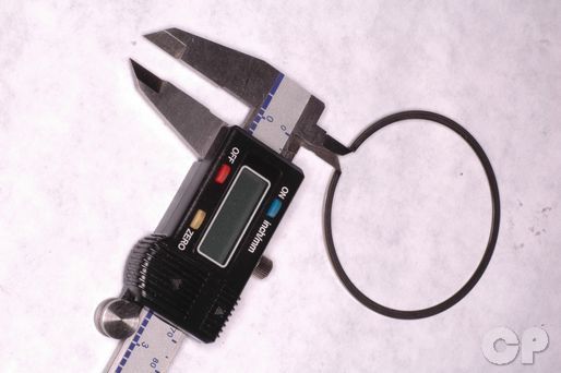
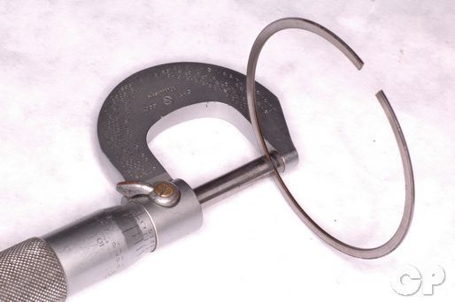
Measure the piston ring free end gap with vernier calipers.
| ITEM | STANDARD mm (in) | LIMIT | ||
| Piston ring free end gap 600 | 1st | R | Approx. 8.6 (0.34) |
6.9 (0.27) |
| Piston ring free end gap 750 | R | Approx. 8.2 (0.32) |
6.6 (0.26) |
|
| Piston ring free end gap 600 | 2nd | RN | Approx. 6.7 (0.26) |
5.4 (0.21) |
| Piston ring free end gap 750 | RN | Approx. 6.9 (0.27) |
5.5 (0.21) |
|
Insert the top ring into the cylinder.
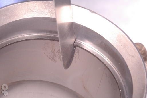
Push the top ring in the cylinder about an inch. Use the piston to push in the ring to keep it square with the cylinder. Measure the ring gap with a feeler gauge. Repeat this procedure with second ring and oil side rails.
| ITEM | STANDARD mm (in) | LIMIT | ||
| Piston ring end gap 600 | 1st | 0.1-0.3
(0.004-0.012) |
0.7
(0.03) |
|
| 2nd 1988 - 1991 |
0.1-0.3
(0.004-0.012) |
0.7
(0.03) |
||
| 2nd 1992 - 1997 |
0.3-0.5 (0.012-0.020) |
0.7
(0.03) |
||
| Piston ring end gap 750 | 1st | 0.10-0.25 (0.004-0.010) |
0.5 (0.02) |
|
| 2nd | 0.2-0.35 (0.008-0.014) |
0.7
(0.03) |
||
Assembly
Clean the piston grooves, and apply fresh engine oil to the piston rings. Spread the rings the minimum amount possible to install them.

Install the oil ring so that the ends are close but not touching. Install the steel rails above and below the oil ring.
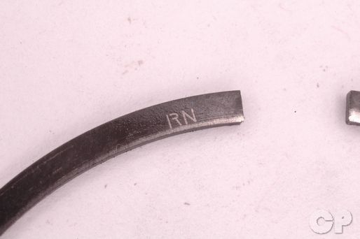
Install the second ring. Its mark should face up. The second ring is marked "RN" on the standard sized rings.
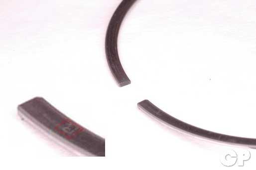
Install the top ring with its mark facing up. The top ring is marked "R" on the standard sized rings.
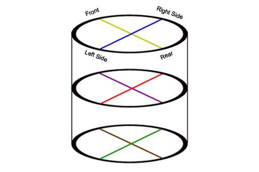
Position the piston ring end gaps as shown.
Inspect the oil jets that sit in the crankcase below the cylinder block for clogs. Clean or replace the oil jets as needed.


Install the pistons to their original locations. Apply fresh engine oil to the piston pin. Install the pistons so that the Arrow mark faces the exhaust side of the engine. Insert the piston pins into the pistons and rods.
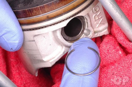


Install new piston pin clips securely into their grooves. Turn the gap in the clips away from the access gap.
Install the dowel pins.
Install a new base gasket. The gasket should be marked which side is up.
Coat the inside of the cylinder, piston rings, and piston in fresh engine oil.
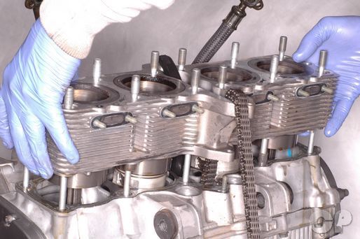


Use a holder tool to compress the rings of the number two and three pistons as you install the cylinder block. Fit pistons two and three into the cylinders. Remove the holder tools and fit them to the number one and four pistons. Install the one and four pistons. Be careful to not damage the rings during this step. Bring the cam chain through the opening.
Install the cylinder head. See the Cylinder Head Installation topic.
Install the cylinder block base nut and tighten it to specification with a 10 mm wrench.
Install the air injection system hoses from the cylinders if your model is equipped with this system. See the Emissions topic for more information.
Install new O-rings onto the oil pipes. Coat the O-rings in Suzuki "A" grease.
Remove the oil pipes from the crankcase.
Install the cylinder head. See the Cylinder Head topic for more information.
Copyright 2025 - Cyclepedia Press LLC

Note: If you are viewing this document offline be sure to visit the latest version online at http://www.cyclepedia.com before attempting any repairs. Updates are made without notice.