Crankshaft and Rods
SAFETY FIRST: Protective gloves and eyewear are recommended at this point.
Removal
Separate the halves of the crankcase. See the crankcase Splitting for more information.


Lift the crankshaft out of the upper crankcase half.
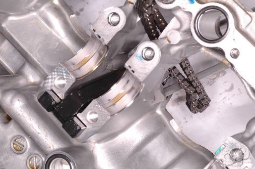
Guide the cam chain out of the upper crankcase half with the crankshaft.


Remove the cam chain from the from the crankshaft.


Remove the dampers from the cam chain guide pivot.


Lift out the cam chain guide and inspect it for excessive wear and damaged.
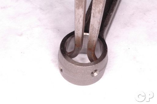
Measure the inside diameter of the small end of the connecting rods.
| ITEM | STANDARD mm (in) | LIMIT |
| Conrod small end I.D. 600 | 18.010-18.018 (0.7091-0.7094) |
18.040 (0.7102) |
| Conrod small end I.D. 750 | 19.010-19.018 (0.7484-0.7487) |
19.040 (0.7496) |
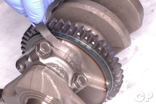
Measure the connecting rod big end side clearance with a feeler gauge.
| STANDARD mm (in) | LIMIT |
| 0.10-0.20 (0.004-0.008) | 0.30 (0.01) |


Before removing the connecting rods mark them to indicate which cylinder they go with. Loosen the connecting rod nuts with a 12 mm socket.
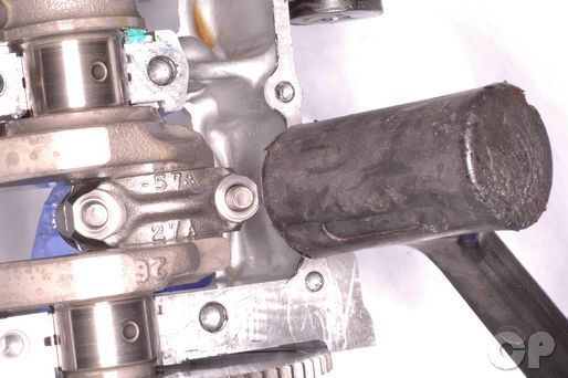
Tap the connecting rod stud lightly to free the bearing cap.


Remove the bearing cap from the bottom of the connecting rod. lift the connecting rod out of the engine.
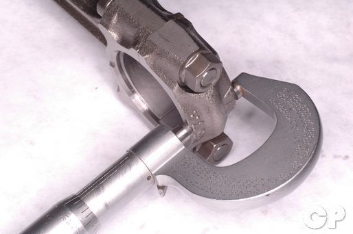
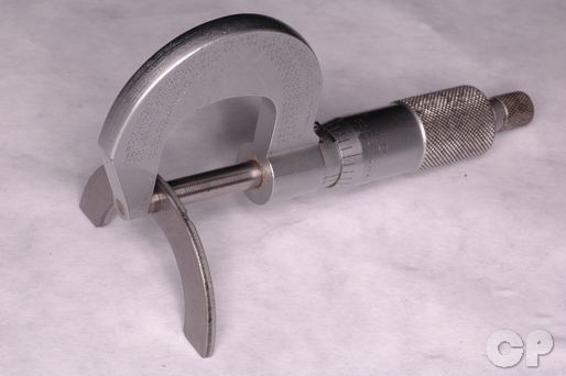
Measure the width of the big end of the connecting rod with a micrometer.
(Connecting Rod Big End Width: 20.95 - 21.00 mm or 0.825 - 0.827 in)
Measure the width of the crank pin with dial calipers.
(Crank Pin Width: 21.10 - 21.15 mm 0.831 - 0.833 in)
Inspect the connecting rod-crank pin bearings for abnormal wear and damage. Replace them according to the connecting rod-crank pin bearing section below.
Connecting Rod-Crank Pin Bearings
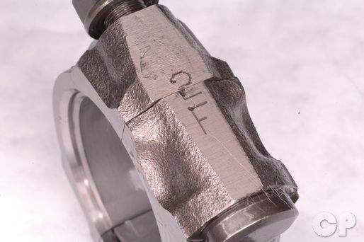
There is a number stamped on the end of the connecting rod to indicate the Inside diameter. Our rod shows a 2.
| Code | Inside Diameter Specification |
| 1 | 37.000 - 37.008 mm (1.4567 - 1.4570 in) |
| 2 | 37.008 - 37.016 mm (1.4570 - 1.4573 in) |
| Code | Inside Diameter Specification |
| 1 | 39.000 - 39.008 mm (1.5354 - 1.5357 in) |
| 2 | 39.008 - 39.016 mm (1.5357 - 1.5360 in) |
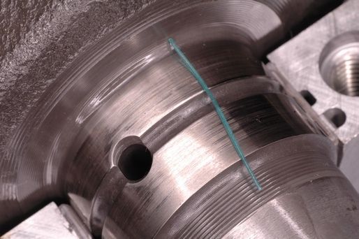
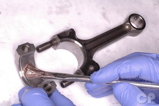
Clean the crank pin-connecting rod journals and bearings using aerosol brake cleaner and a lint free cloth. Break off a short length of Plastigauge and lay it on the connecting rod journal. Avoid the oil hole location.
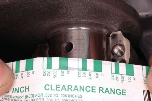
Install the connecting rod to the crankshaft and check the plastigauge according to its clearance chart. See Below to install the connecting rod. Measure at the widest section of the plastigauge for an accurate measurement. Do not rotate the crankshaft and rod while the plastigauge is being used. Remove the plastigauge when finished.
| STANDARD mm (in) | LIMIT |
| 0.032-0.056 (0.0013-0.0022) | 0.080 (0.0031) |
Special Tools- Plastigauge 09900-22301
If the oil clearance reading exceeds the service limit the bearings must be replaced as a set.
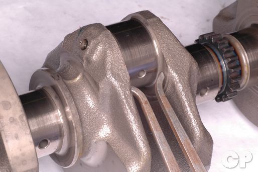
The crank pin outside diameter codes are printed on the second crank weight from the right. The code is a combination of four numbers containing only the digits 1, 2, or 3. This code gives the outside diameter of the crank pins from left to right.
If the code cannot be read you can measure the diameter of the of the crank pins with a micrometer.
| Codes | Outside Diameter mm (in) |
| 1 | 33.992 - 34.000 (1.3383 - 1.3386) |
| 2 | 33.984 - 33.992 (1.3380 - 1.3383) |
| 3 | 33.976 - 33.984 (1.3376 - 1.3380) |
| Codes | Outside Diameter mm (in) |
| 1 | 35.992 - 36.000 (1.4170 - 1.4173) |
| 2 | 35.984 - 35.992 (1.4167 - 1.4170) |
| 3 | 35.976 - 35.984 (1.4164 - 1.4167) |
Select the proper bearing according to the chart. The bearings for all rods should be replaced as a set.
| Crank Pin Outside Diameter | ||||
| Code | 1 | 2 | 3 | |
| Connecting Rod Inside Diameter |
1 | Green | Black | Brown |
| 2 | Black | Brown | Yellow | |
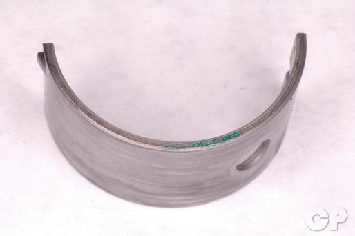
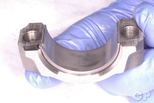
This is an example of a green bearing.


Install the bearing tab first and then press in the other end of the bearing.
Crankcase-Crankshaft Bearings
Note: Do not remove the crankshaft journal bearings unless necessary. See the Inspection section below for more information.


Inspect the crankcase-crankshaft bearings for abnormal wear and damage. Replace the bearings according to the section below.
Break off a short length of plastigauge and lay it on the crankshaft journal. Avoid the oil hole location.
Install the crankcase halves together and tighten the 12 bolts to specification as described in the Crankcase Assembly topic. Separate the crankcase halves and inspect the plastigauge according to its clearance chart. Measure at the widest section of the plastigauge for an accurate measurement. Do not rotate the crankshaft while the plastigauge is being used. Remove the plastigauge when finished.
| STANDARD mm (in) | LIMIT |
| 0.020-0.044 (0.0008-0.0017) | 0.080 (0.0031) |
Special Tools- Plastigauge 09900-22301
If the oil clearance reading exceeds the service limit the bearings must be replaced as a set.
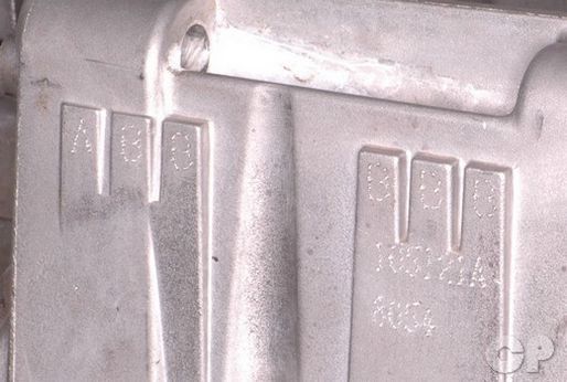
On the back side of the upper crankcase the codes for the crankcase journal inside diameter are inscribed.
| Code | Inside Diameter Specification |
| A | 35.000 - 35.008 mm (1.3780 - 1.3783 in) |
| B | 35.008 - 35.016 mm (1.3783 - 1.3786 in) |
| Code | Inside Diameter Specification |
| A | 39.000 - 39.008 mm (1.5354 - 1.5357 in) |
| B | 39.008 - 39.016 mm (1.5357 - 1.5360 in) |
The crankshaft journal outside diameter codes are printed on the far right crank weight. The code is a combination of six letters containing only the characters A, B, and C. This code gives the outside diameter of the crankshaft journals from left to right.
If the code cannot be read you can measure the diameter of the of the crankshaft journals with a micrometer.
| Code | Outside Diameter Specification mm (in) |
| A | 31.992 - 32.000 (1.2595 - 1.2598) |
| B | 31.984 - 31.992 (1.2592 - 1.2595) |
| C | 31.976 - 31.984 (1.2589 - 1.2592) |
| Code | Outside Diameter Specification mm (in) |
| A | 35.992 - 36.000 (1.4170 - 1.4173) |
| B | 35.984 - 35.992 (1.4167 - 1.4170) |
| C | 35.976 - 35.984 (1.4164 - 1.4167) |
Select the proper bearings based on the crankshaft and crankcase journal codes.
| Crankshaft Outside Diameter | ||||
| Code | A | B | C | |
| Crankcase Inside Diameter |
A | Green | Black | Brown |
| B | Black | Brown | Yellow | |


Remove and clean the oil jets in the upper crankcase before installing the new bearings. Return the oil jets to the crankcase with new O-rings.
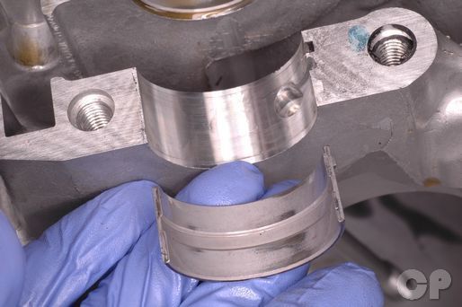

Install the correct thickness of bearing. The lower crankcase bearings have oil holes. Install the bearing tab first and then press in the other end of the bearing.
Crankshaft Thrust Bearings
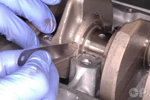
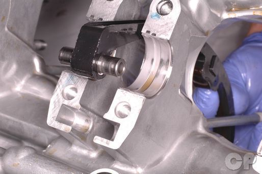
With the bearings and crankshaft installed pull the crankshaft to the left so that there is no clearance between the crankshaft and the right thrust bearing. Measure the clearance between the left thrust bearing and the crankshaft with a feeler gauge.
| MODEL | SPECIFICATION mm (in) |
| 600 | 0.04-0.09 (0.002-0.004) |
| 750 | 0.05-0.13 (0.002-0.005) |

If the clearance is out of specification remove the crankshaft and thrust bearings.
Measure the thickness of the right thrust bearing with a micrometer. If the right thrust bearing fails to meet the standard replace it with a new item and recheck the clearance.
| MODEL | STANDARD mm (in) |
| 600 | 2.445 - 2.465 (0.0963 - 0.0970) |
| 750 | 2.422 - 2.44 (0.095 - 0.096) |
If the clearance is still out of specification with a new right bearing the left bearing must be replace with a suitable part.
Measure the left side thrust clearance without the left thrust bearing installed. Use the chart to pick the appropriate left bearing.
| Clearance Without Left Thrust Bearing |
Color (Part Number) |
Thrust Bearing Thickness |
| 2.415 - 2.440 mm (0.0951 - 0.0961 in) |
Red (12228-43411) |
2.350 - 2.375 mm (0.0925 - 0.0935 in) |
| 2.440 - 2.465 mm (0.0961 - 0.0970 in) |
Black (12228-43412) |
2.375 - 2.400 mm (0.0935 - 0.0945 in) |
| 2.465 - 2.490 mm (0.0970 - 0.0980 in) |
Blue (12228-43413) |
2.400 - 2.425 mm (0.0945 - 0.0955 in) |
| 2.490 - 2.515 mm (0.0980 - 0.0990 in) |
Green (12228-43414) |
2.425 - 2.450 mm (0.0955 - 0.0965 in) |
| 2.515 - 2.540 mm (0.0990 - 0.1000 in) |
Yellow (12228-43415) |
2.450 - 2.475 mm (0.0965 - 0.0974 in) |
| 2.540 - 2.565 mm (0.1000 - 0.1010 in) |
White (12228-43416) |
2.475 - 2.500 mm (0.0974 - 0.0984 in) |
| Clearance Without Left Thrust Bearing |
Color (Part Number) |
Thrust Bearing Thickness |
| 2.440 - 2.49 mm (0.096 - 0.098 in) |
Black (12228-48B00-0H0) |
2.36 - 2.38 mm (0.093 - 0.094 in) |
| 2.490 - 2.54 mm (0.0980 - 0.1 in) |
Green (12228-48B00-0E0) |
2.42 - 2.44 mm (0.095 - 0.096 in) |
| 2.540 - 2.59 mm (0.1000 - 0.1020 in) |
Red (12228-48B00-0C0) |
2.46 - 2.48 mm (0.097 - 0.098 in) |
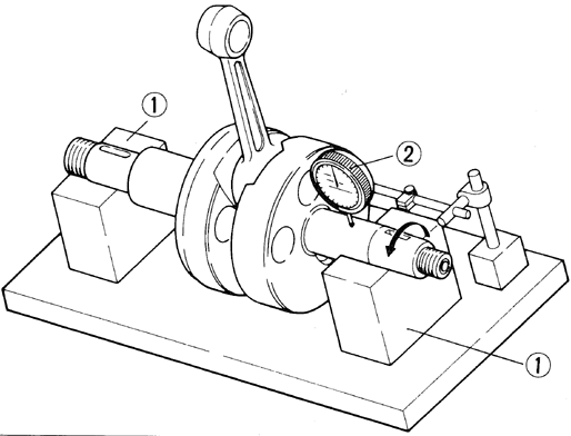
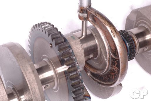
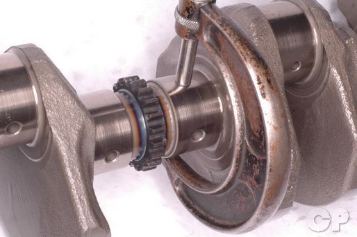
Place the crankshaft on V-block. Measure the runout with a dial gauge and a magnetic stand. Position the dial gauge so that it touches the crankshaft journal next to the cam chain sprocket. Turn the crankshaft over slowly and inspect the runout.
(Crankshaft Runout Service Limit: 0.05 mm or 0.002 in)
Special Tools-
Dial Gauge (1/100 mm): 09900-20606
Magnetic Stand: 09900-20701
V-Block Set (100 mm): 09900-21304
Installation
Install the correct bearings as discussed above. Coat the bearings' surface with a mixture of fresh engine oil and moly paste (1 to 1 ratio).
Suzuki Moly Paste: 99000-25140
Install the rear cam chain guide.
Set the dampers over the cam chain guide pivot.
Place the cam chain around its drive sprocket on the crankshaft.
Lower the crankshaft into the upper crankcase half. Guide the cam chain through its opening as the crankshaft fits into the crankcase half.
Return any removed rods to their original position on the crankshaft.
The numbers on the side of the large end of the connecting rod should face towards the intake side of the engine.
Thread on the connecting rod nuts. Tighten the nuts evenly to the initial torque specification. Tighten them to the final torque specification with a 12 mm socket.
(Connecting Rod Nut Initial Torque: 20 N-m or 14.5 lb-ft)
(600 Connecting Rod Nut Final Torque: 35 N-m or 25.5 lb-ft)
(750 Connecting Rod Nut Final Torque: 49 - 53 N-m or 35.5 - 38 lb-ft)
Assemble the crankcases. See the Crankcase Assembly topic for more information.
Copyright 2025 - Cyclepedia Press LLC

Note: If you are viewing this document offline be sure to visit the latest version online at http://www.cyclepedia.com before attempting any repairs. Updates are made without notice.