Switches
SAFETY FIRST: Protective gloves and eyewear are recommended at this point.
To test these switches, you will need a digital multimeter set to Ω (Ohms of resistance). If a switch does not meet specification replace it. The switch continuity diagrams are also shown on the wiring diagrams.
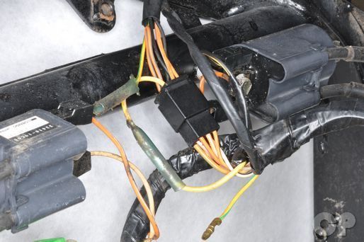
Ignition Switch
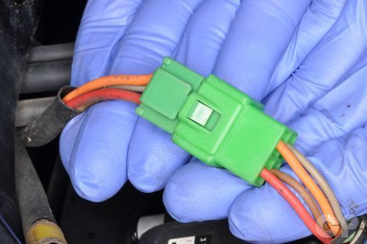


The ignition switch connector is located near the front of the frame. Unplug the ignition switch. Check for continuity between the wires on the switch side as indicated-
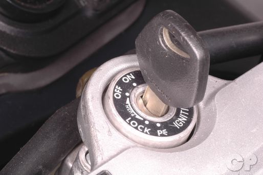
ON position
- red and orange
- gray and brown
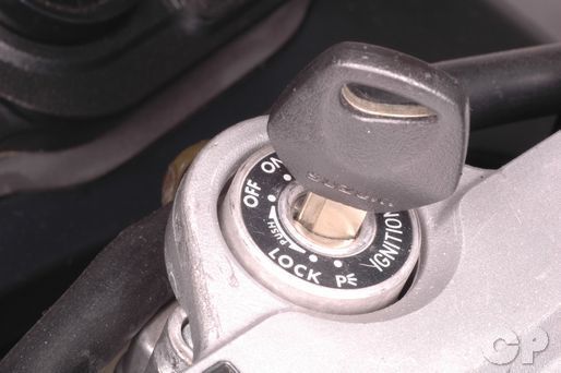
OFF position
- No continuity
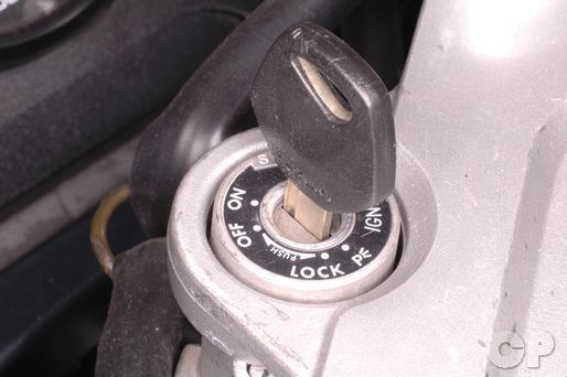
P position
- Red and Brown
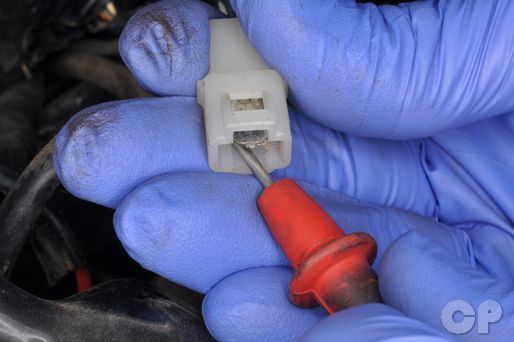
Handlebar switches


Unplug the yellow left handlebar switch connector.


Unplug the black right handlebar switch connector.


Check the handlebar switches for continuity as indicated-
Engine Start and Stop Switch
RUN position
- orange/black and orange/white
OFF position
- No continuity
Starter Button
PUSHED IN
- orange/white and yellow/green
FREE
- No continuity
Front Brake Switch
ON
- orange/green and white/blue
FREE
- No continuity
Dimmer Switch
HI Position
- yellow and yellow/white
LO position
- white and yellow/white
Turn Signal Switch
LEFT turn
- light blue and black
PUSH (release)
- No continuity
RIGHT turn
- light green and light blue
Clutch switch
PULLED IN
- yellow/green and yellow/green
FREE
- No continuity
Horn Button
PUSHED IN
- black/white and green
FREE
- No continuity
To remove the handlebar switches see the Handlebar topic.
Neutral Switch
Remove left the side fairings. See the Fairings topic for more information.
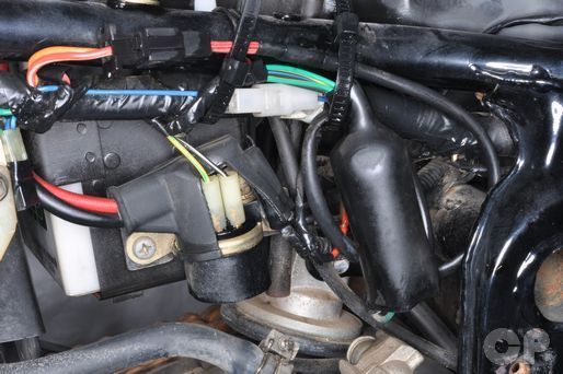


Free the wire bands from the frame.


Unplug the neutral switch connector.
Measure the resistance between the blue neutral switch connector and a ground. There should be continuity in neutral and no continuity in gear.
To remove the neutral switch see the Crankcase Splitting topic for more information.
Side Stand Switch
Remove left the side fairings. See the Fairings topic for more information.
Free the wire bands from the frame.


Disconnect the side stand switch connectors.
Check for continuity between the connectors the side stand in the up and down position. There should be continuity when the stand is up and none when down.
Rear Brake Switch


Unplug the rear brake switch connector. Check for continuity between the orange/green wire and the white/black wire. Continuity should exist when the pedal is depressed, and not when the pedal is released. Adjust the switch if necessary. See the Rear Brake Inspection topic for more information.
Oil Pressure Switch
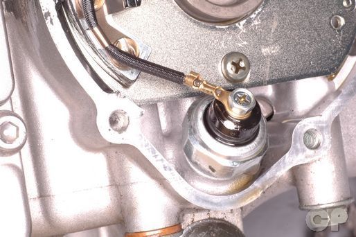
Make sure the oil level is in specification before checking the oil pressure switch. See the Engine Oil topic for more information.
There should be continuity between the green/yellow wire and an engine ground. There should not be continuity when the engine is stopped.
To remove the oil pressure switch see the Signal Generator topic for more information
Copyright - Cyclepedia Press LLC

Note: If you are viewing this document offline be sure to visit the latest version online at http://www.cyclepedia.com before attempting any repairs. Updates are made without notice.